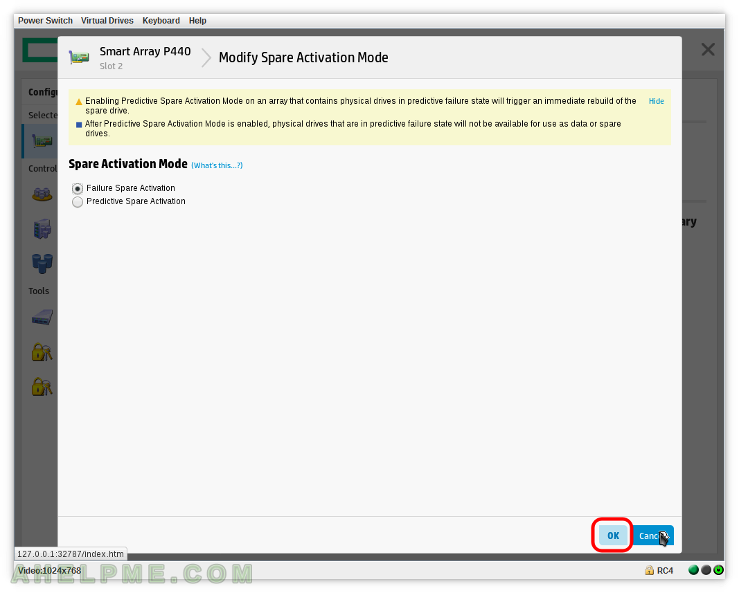
SCREENSHOT 41) Select when to replace a failed disk on failure or the controller to try predicting the failure of a disk.
There two options here: Failure Spare Activation and Predictive Spare Activation.
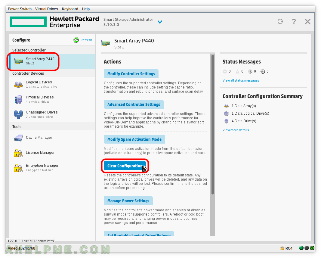
SCREENSHOT 42) Click on the controller Smart Array P440 on the left and then click on “Clear Configuration”. Resets the controller’s configuration to its default state.
Remove all existing arrays and logical drives – data loss!
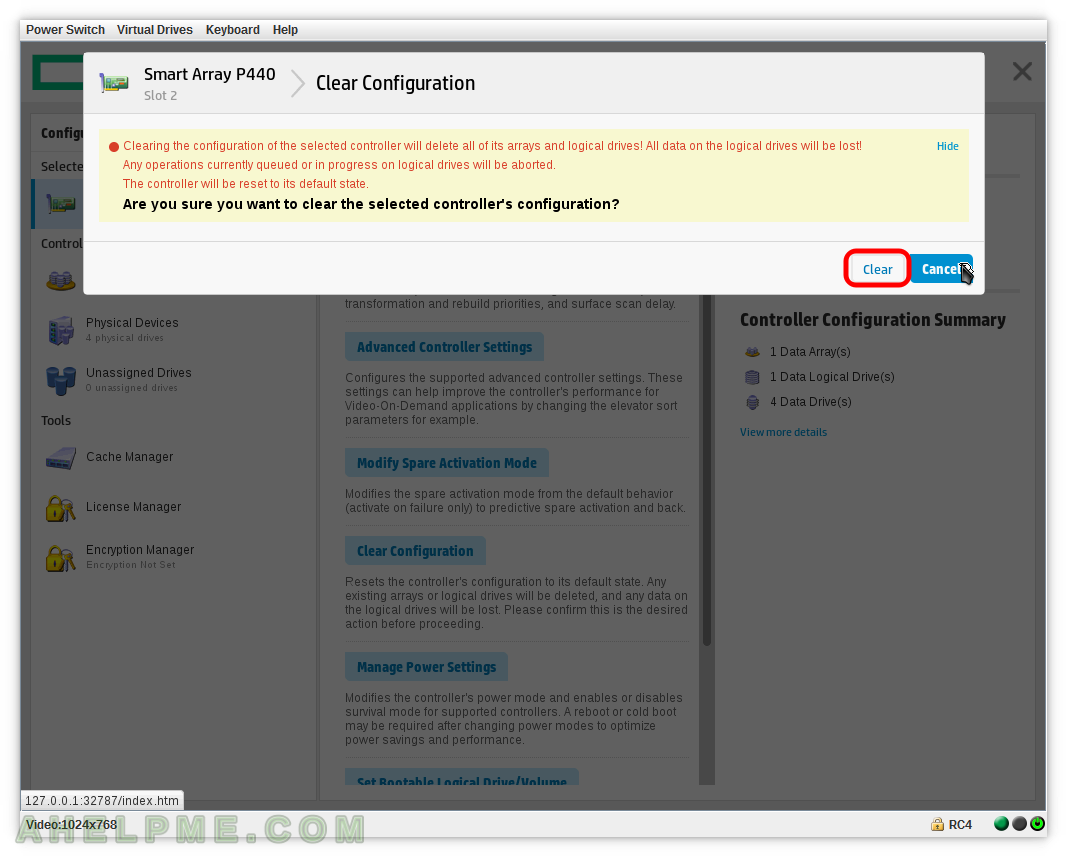
SCREENSHOT 43) Additional confirmation is required before proceeding in clearing the controller’s configuration.
The controller will be reset to its default state!
SCREENSHOT 44) Click on the controller Smart Array P440 on the left and then click on “Manage Power Settings”.
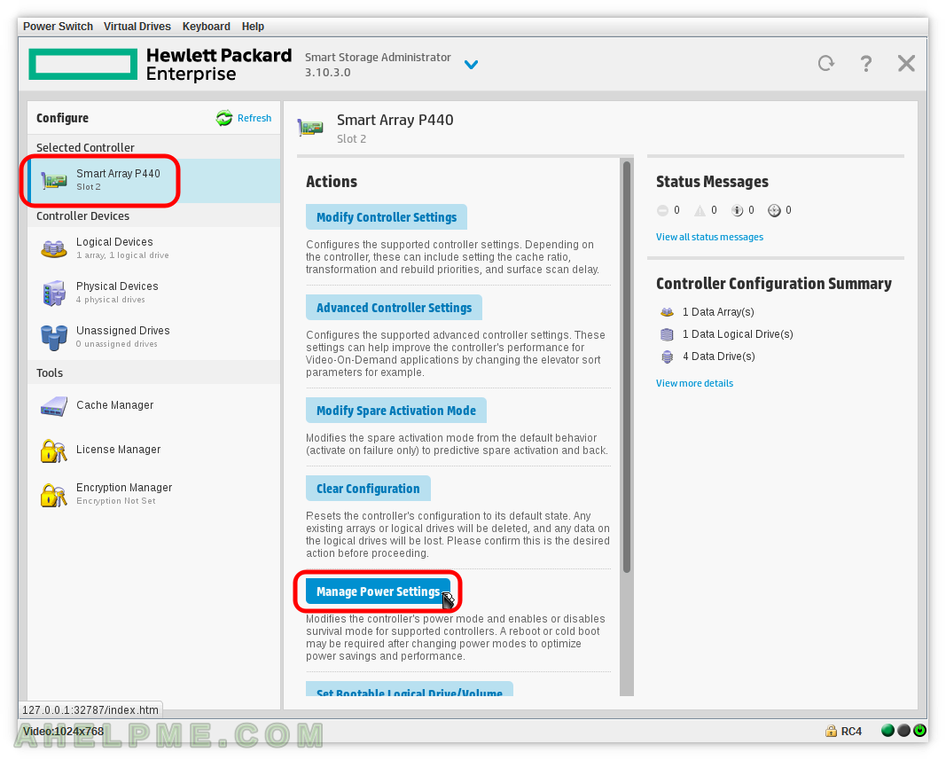
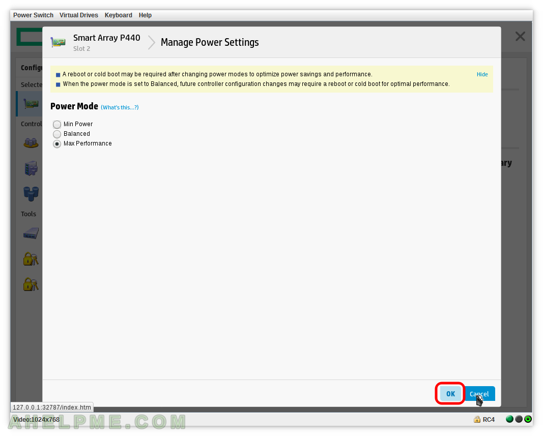
SCREENSHOT 45) Manages the controller’s power mode and enables or disables the survival mode.
The three power modes are Min Power, Balanced and Max Performance.
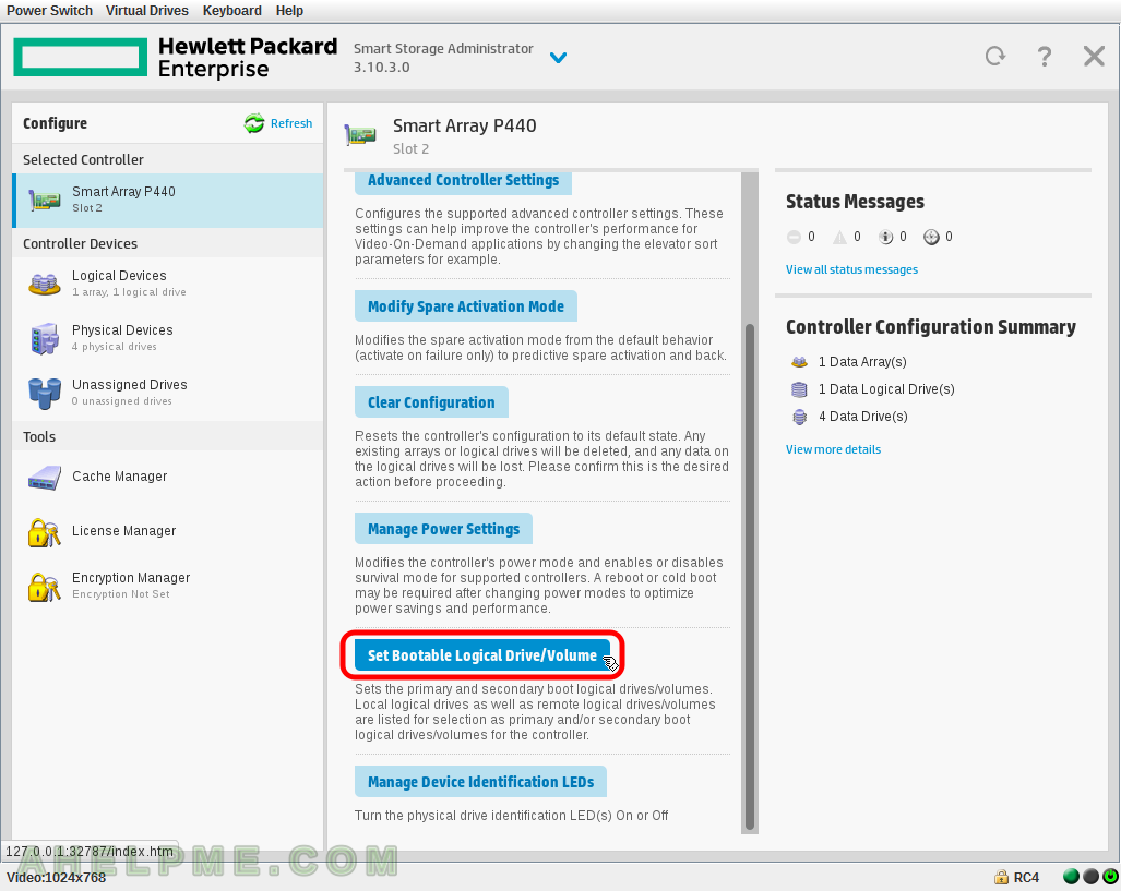
SCREENSHOT 46) Click on the controller Smart Array P440 on the left and then click on “Set Bootable Logical Drive/Volume”.
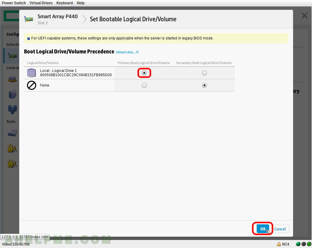
SCREENSHOT 47) Set Primary Boot Logical Boot/Volume and Secondary Boot Logical Boot/Volume.
The boot order when probing to boot from the controller. Set the device and click on “OK”.
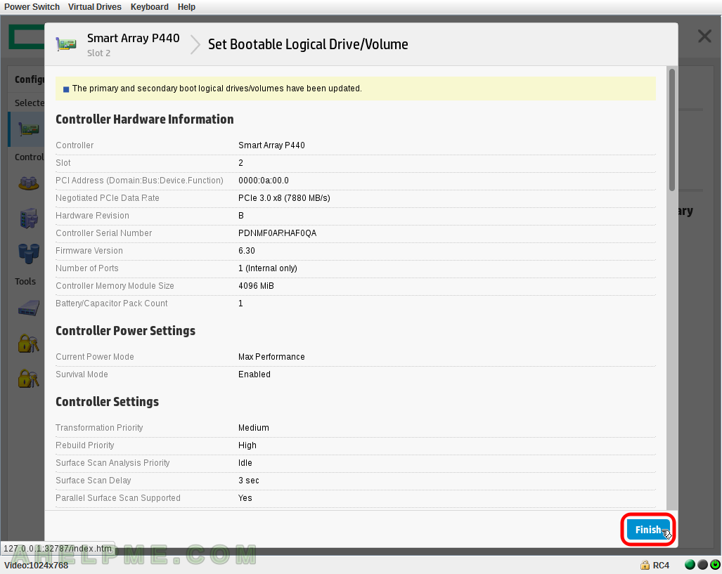
SCREENSHOT 48) Confirmation for the Boot order and controller hardware information.
Click on “Finish”
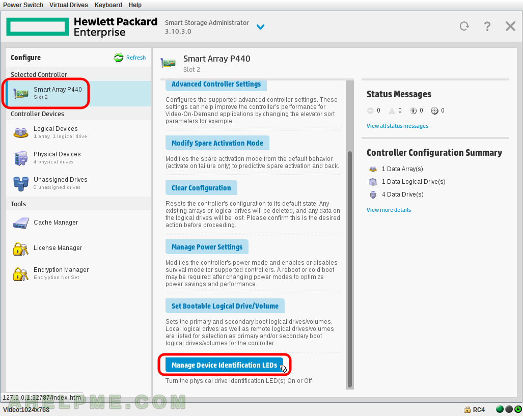
SCREENSHOT 49) Click on the controller Smart Array P440 on the left and then click on “Manage Device Identification LEDs”.
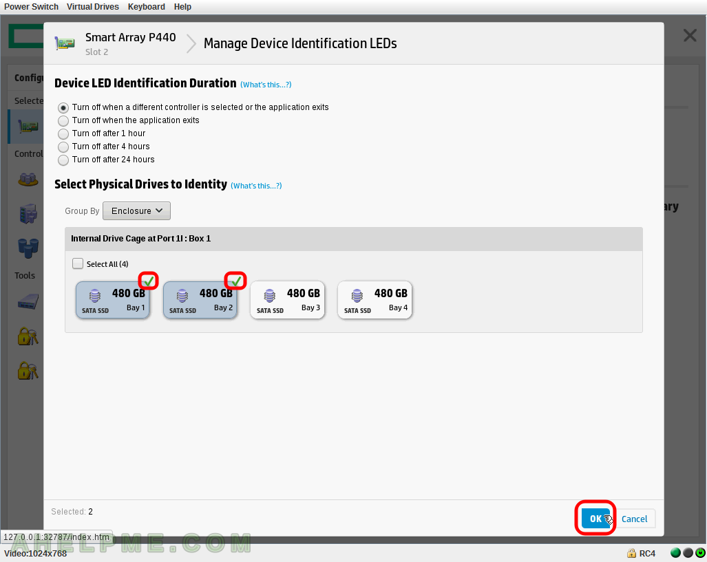
SCREENSHOT 50) LED identification duration – 5 duration types
They are “Turn off when a different controller is selected or the application exits”, “Turn off when the application exits”, “Turn off after 1 hour”, “Turn off after 4 hours”, “Turn off after 24 hours” – they are self-explanatory. Select the drive to switch on the LED identification and then click on “OK”.
